
| Previous Top Next |
| Building the Controller - Inputs and Maneuver Direction |
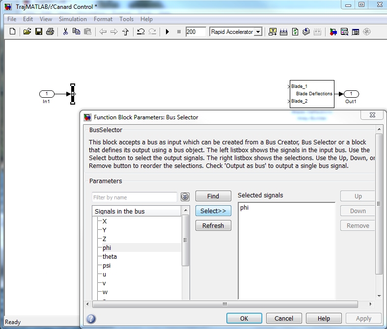
Now that we have our inputs and outputs available we will be working within the Canard Control block to add the control logic. First we must get the Roll Angle from the body state vector "x" that we have as an input. A "Bus Selector" is used to select the desired signal from a bus.
Open the Library Browser and drag a "Bus Selector" from the "Commonly Used Blocks" menu into the Canard Control window. Connect the output from "In1" to the input of the "Bus Selector". Then open (double click) the bus selector. All signals contained on the bus are listed at the left. Highlight "phi" (the roll angle) and click select. This adds the signal to the Selected Signals box on the right. Next select and remove the two default signals in this box leaving only "phi" and click OK.

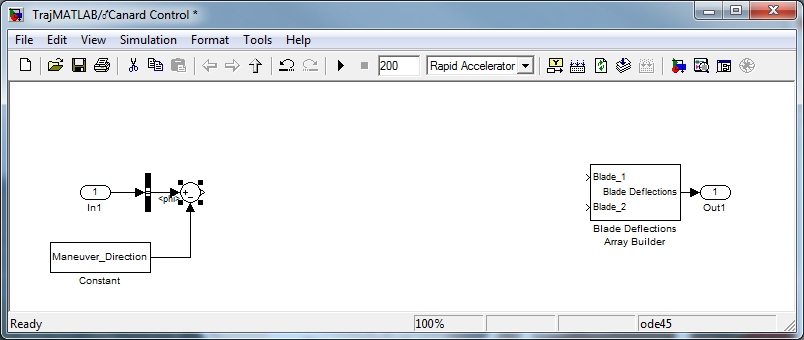
Next we'll need to control the phase of the Canard oscillation. To do this, we'll start by defining a constant called Maneuver_Direction. Drag a Constant Block from the Library Browser, Commonly Used Blocks folder and set the value to Maneuver_Direction. Double click on the Constant to access the value field. We'll need to define this variable in the MATLAB workspace in order for Simulink to be able to use it. We'll do that later.
Now we'll generate the error between the maneuver direction and the projectile's roll angle using a Sum Block. The Sum Block is also found in the Commonly Used Blocks folder of the Library Browser. Note that you will need to open the Sum Block to change the sign of the Maneuver Direction signal to negative. Your block diagram should now look like the one below.

| © 2011 Arrow Tech Associates |