
| Previous Top Next |
| Building the Controller - Adding a Switch |
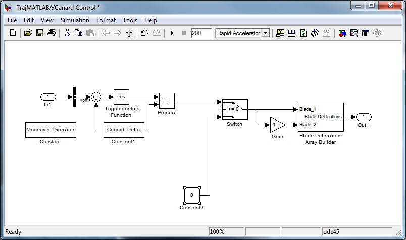
Now we'll add a switch with the capability to control when the maneuver begins and also to turn the control system on and off. First, drag a Switch from the Library Browser (Signal Routing menu) to the block diagram and connect it so that the oscillating signal goes in the top input and the output goes to the blades as before. Then add another constant equal to zero and connect this to the second input of the switch as shown below. This input will be used when the control system is off.

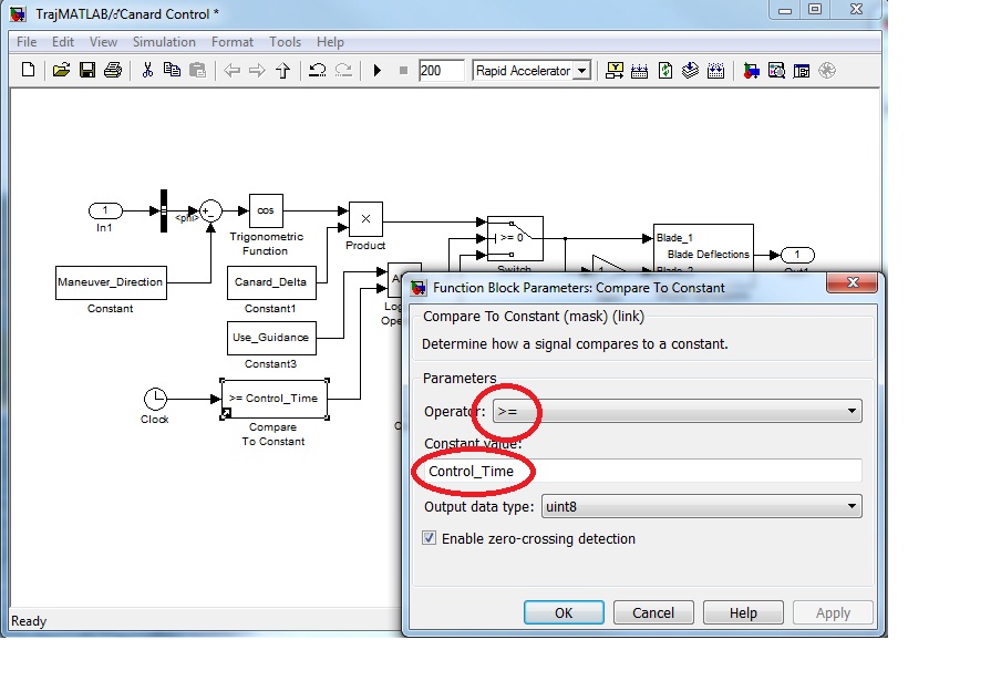
Now we need to add the control to turn the switch on and off. There will be two conditions that must both be satisfied to turn the switch on. We'll use the logical AND operator to combine these two conditions. Drag an AND Block from the Library Browser (Logic and Bit Operations menu) and connect it to the second input on the Switch. Then create another constant with the value equal to "Use_Guidance". Connect this to the first input on the AND operator. This constant will be used to turn guidance on or off.
Now all that remains is to determine if we are past the time when we want to turn on guidance. We'll need a Clock from the Sources menu in the Library Browser. Then we'll use a Compare to Constant Block from the Logic and Bit Operations menu in the Library Browser to perform the logical test. Open the Compare To Constant block and set it to check if the time is greater than or equal to a variable called Control_Time as shown below.

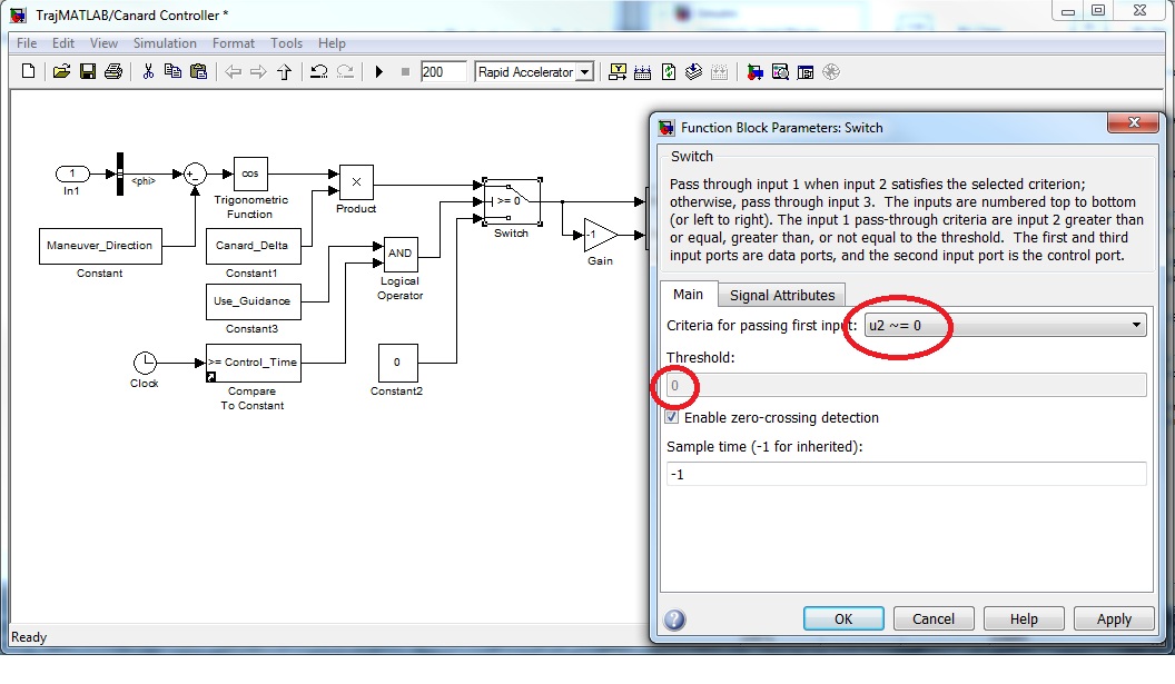
Now double click on the Switch so we can set that up properly. The output of the Compare to Constant Block will be zero when the result of the logical test is False and 1 when the result is true. We'll set the variable Use_Guidance to "1" to turn guidance on and to "0" otherwise. The AND operator has a Boolean output that will be "1" when both inputs equal "1" and "0" otherwise. We'll set the Switch so that the first input is passed when the control input is not equal to zero.

| © 2011 Arrow Tech Associates |